Disclaimer: The opinions expressed in this blog post are my own and not a reflection of VMware or Dell Technologies.
This is the first post in a series documenting how I have NSX-T configured in my Home SDDC environment and working (initially) with Enterprise PKS.
NSX-T is not NSX-v
Let’s just get that out of the way right now. The two products, although they share a common name, are almost nothing alike when you drill down into the design and implementation. The functionality between the two products is nearly aligned, and the high-level concepts (SDN, DFW, Security Tags, etc.) are all there, but the practical implementation of these concepts is drastically different.
The hardest part for me in adopting NSX-T in my own SDDC environments has been that it felt like I needed to throw out all of my NSX-v knowledge and start over completely.
Having said that, it’s the direction VMware is moving with SDN and NSX-T is indeed the future — so get on the bus!
Home SDDC Network Logical Design
As a previous post detailed, my Home SDDC Lab is relatively basic. It’s purpose built for me to play with all the new tech coming out of VMware and be able to validate reference architectures, operational procedures and deployment automation. It’s nothing like what a production-grade enterprise environment would look like — my budget is a rounding-error for some organizations.
That being said, here is what I laid out to accomplish in my SDDC with NSX-T:

Breaking down the diagram a bit, here are a few key items:
- Each Dell R640 node has 4x1GbE NICs.
- Two (vmnic0 & vmnic1) are attached to a typical vCenter Server Virtual Distributed Switch.
- Two (vmnic2 & vmnic2) are dedicated to NSX-T and attached to the N-VDS.
- The Cisco Catalyst 3560G L3 Switch has 2 VLANs for the TEPs that NSX-T requires. Each VLAN has a routed interface on the Catalyst.
- The NSX Edge VMs (edge01 & edge02) have a management interface on the VDS portgroup, and an interface on the VDS portgroup for the TEP VLAN.
- There are 2 NSX-T Transport Zones – TZ-OVERLAY and TZ-VLAN.
- The TZ-VLAN transport zone is used for the P2V uplink connection between the T0 Router and the Catalyst switch.
- The TZ-OVERLAY transport zone is used for all of the T1 Router VM networks.
- There are 4 NSX-T Network Segments – TZ-Uplink-1, TZ-PKS-Segment, TZ-K8S-1-Segment & TZ-K8S-2-Segment.
- TZ-Uplink-1 is attached to the TZ-VLAN transport zone.
- The other 3 are all attached to the TZ-OVERLAY transport zone.
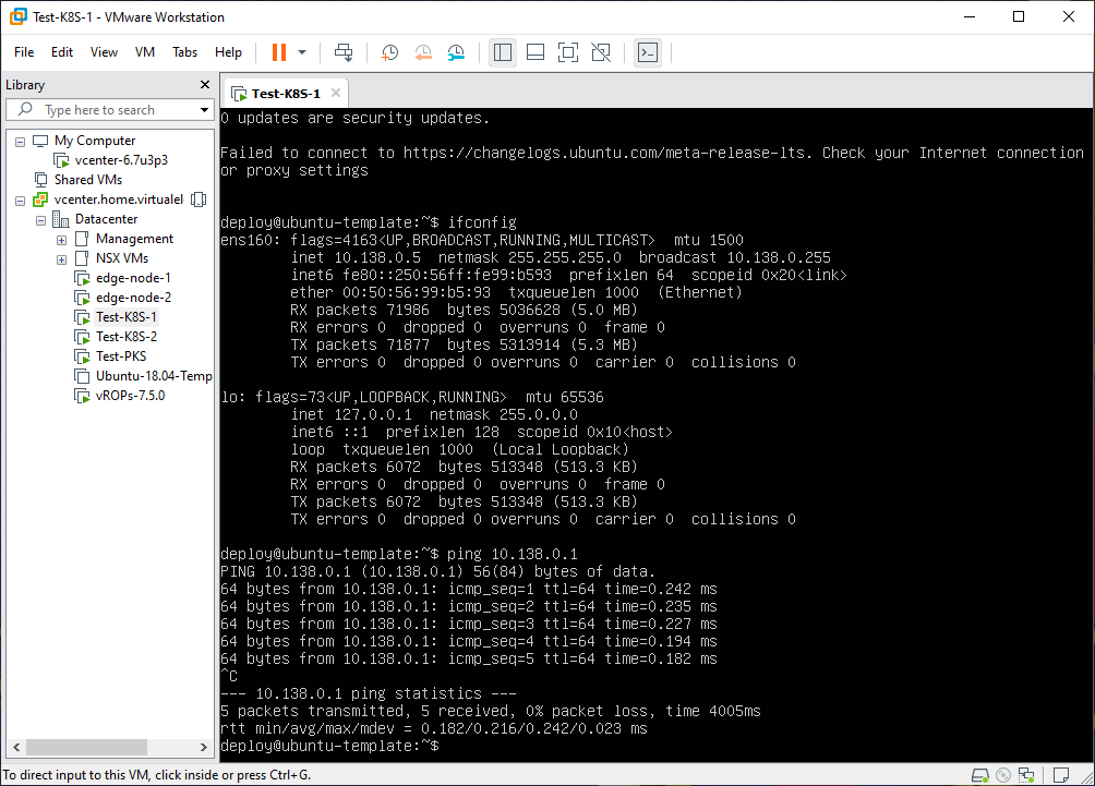
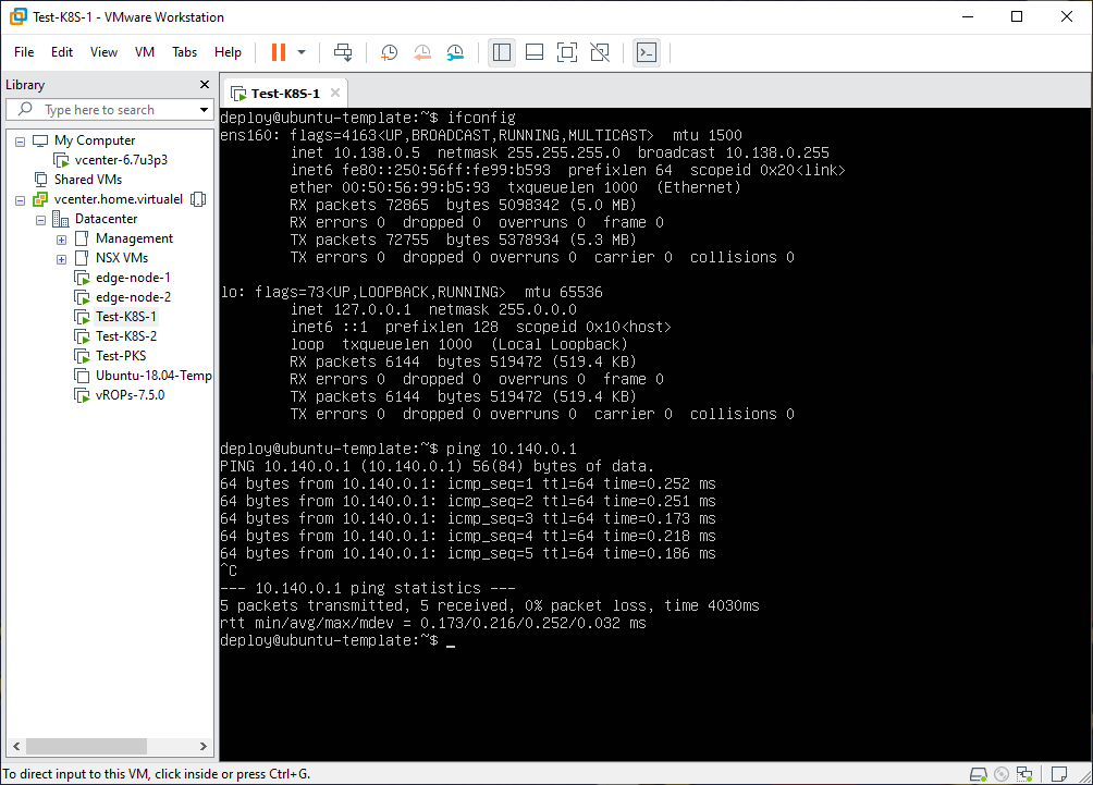
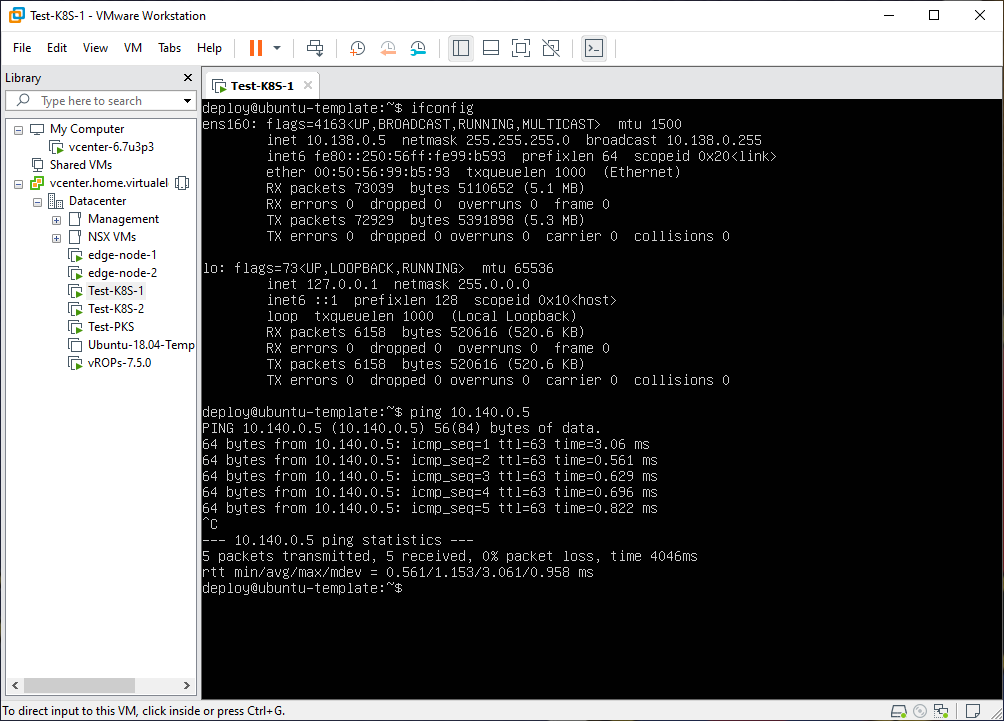
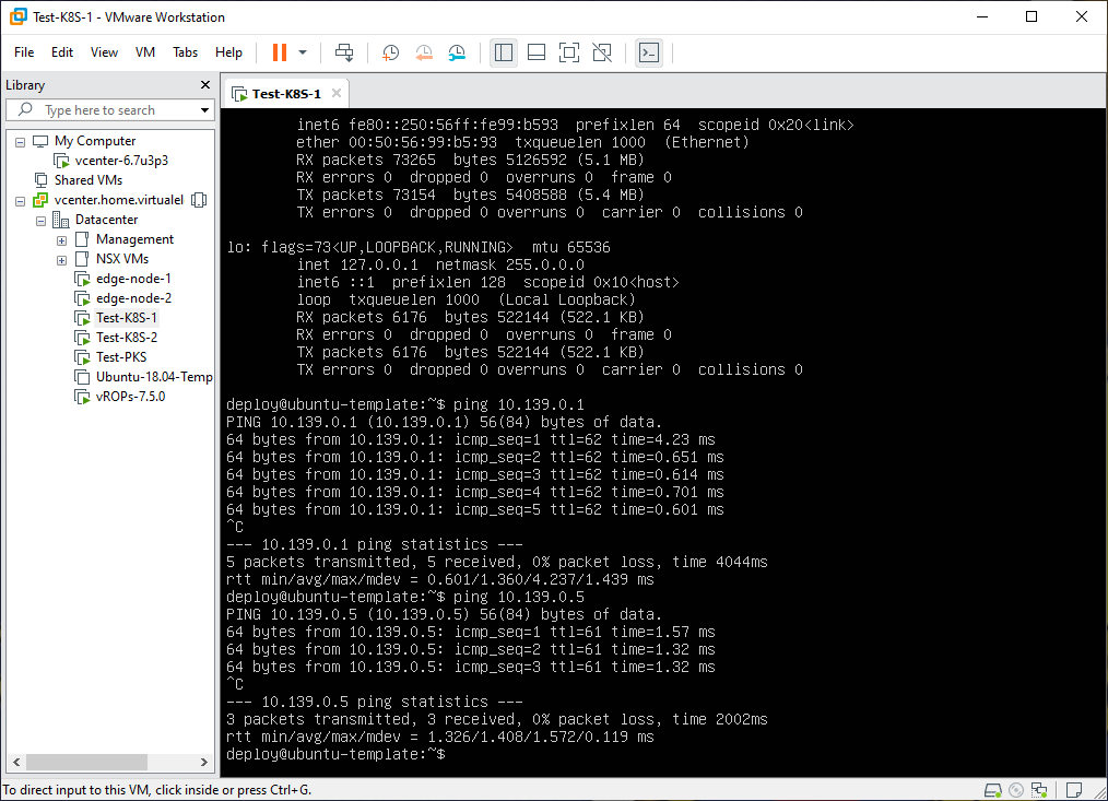
Connectivity Testing
With the initial NSX-T components and test VMs deployed (and attached to each of the 3 overlay segments) it was time to test connectivity to validate things were configured properly.
Next Steps
By far the largest challenge the past few days has been to piece together all of the different documentation versions, community blog posts, and official PKS documentation reference architectures into a single, cohesive method for configuring the environment. The number of changes from my early days with NSX-T (v1.9) to the current version v2.5.0 that is running is staggering, as such much of the documentation available at this time was incomplete or no longer accurate. The next blog post will walk through the configuration steps, with screenshots for NSX-T v2.5.0, for setting up all the components.
Enjoy!